

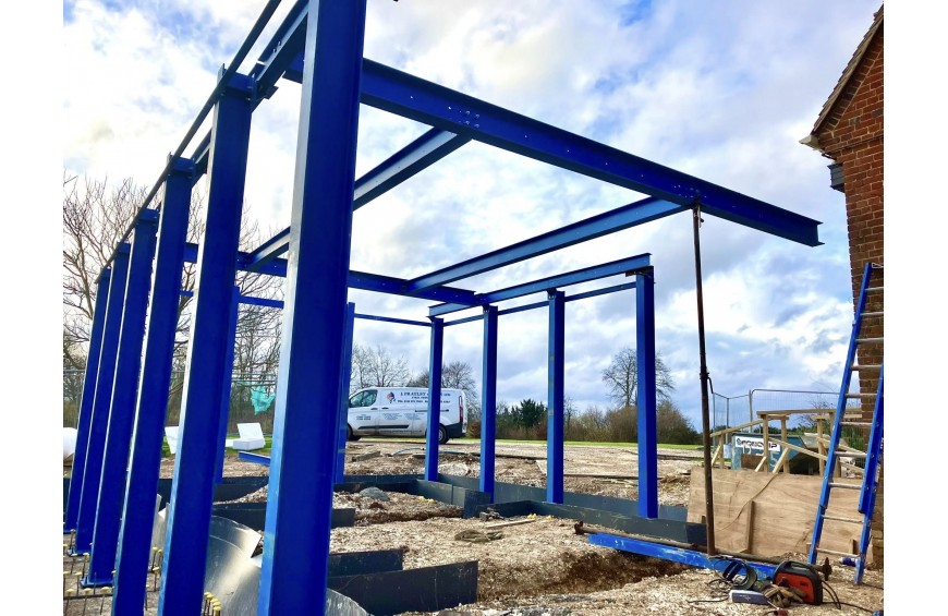
The steel beam is the permanent solution. It's what stays in your building for decades supporting loads above. But before that permanent beam gets installed, something else must support those same loads temporarily—often for hours or days while the permanent structure is prepared. This temporary support phase—using acrow props, strongboys, needles, and dead shores—represents the most structurally critical and dangerous period of any beam installation project. Yet it's the phase that receives least attention in planning and often gets executed poorly through misunderstanding of what these temporary works actually do.
The wall comes down. Loads that were distributed across meters of masonry now concentrate onto a handful of adjustable props. The floor or roof above—potentially carrying furniture, people, building materials, roof tiles, and structural dead load—hangs on temporary supports that must perform perfectly while permanent supports are installed. Get temporary works wrong and the consequences range from minor cracking to catastrophic collapse, with the structural failure occurring not when the beam is installed but before, during the temporary phase when loads are most vulnerable.
For builders, self-builders, and developers across the UK undertaking structural alterations involving steel beams, understanding temporary supports transforms them from mysterious scaffolding poles into the critical load-bearing systems they actually are. Because the steel beam specification might be perfect, the structural calculations flawless, and the installation exemplary—but if temporary supports fail during the hours between removing the load-bearing wall and installing the beam, none of that matters. The building has already failed.
This analysis explains what temporary supports actually do structurally, describes the equipment and methods used for different situations, demonstrates what happens when temporary works fail and why, quantifies the risks and costs of inadequate temporary support, and provides practical guidance ensuring temporary support adequacy during your beam installation project.
What Temporary Supports Actually Do: The Structural Reality
Temporary supports don't just "hold things up while you work." They perform specific structural functions replicating what the permanent beam will eventually do.
Load Transfer During Removal
Before removal:
- Load-bearing wall distributes loads from above across its entire length
- Load path: Floor/roof → joists → wall plate → masonry wall → foundations
- Load spreads through wall thickness and height
- Each meter of wall carries approximately equal proportion of total load
During removal (with temporary supports):
- Wall no longer exists as load path
- Loads must transfer to temporary support points
- Load path: Floor/roof → joists → temporary support → temporary foundation (usually existing floor slab)
- Concentrated point loads instead of distributed line loads
The critical difference: Wall supports loads continuously and uniformly. Temporary supports create point loads at specific locations. The structure above must span between these points without the wall it was designed to rest upon.
Example: Removing 4-meter load-bearing wall
Original condition:
- Load above: 40 kN total (approximately 4 tonnes)
- Distributed uniformly: 10 kN per meter of wall
- Each brick pier carries small proportion, loads spread through masonry
Temporary support condition:
- Same 40 kN total load
- Supported at 3 points (props at 0m, 2m, 4m)
- Each prop carries ~13 kN (1.3 tonnes)
- Floor joists above must span 2 meters between props instead of continuous bearing on wall
- Joists experience higher bending stress than original design
What this means: Temporary supports don't just replace the wall—they fundamentally change how loads transfer. The structure above must be capable of spanning between support points. If support spacing exceeds joist span capacity, failure occurs even with adequately strong props.
The Three Support Functions
Effective temporary works provide:
1. Vertical support (preventing downward movement):
- Props must carry full load without compressing, buckling, or settling
- Foundation (floor slab or pads) must withstand concentrated prop loads
- Support height must remain constant (props must not shorten under load)
2. Lateral restraint (preventing sideways movement):
- Walls and structures tend to move laterally when supporting wall removed
- Temporary works must prevent this movement
- Particularly critical for party walls and gable ends
3. Load redistribution (spreading concentrated loads):
- Props create point loads; these must spread to avoid punching through floors
- Spreader plates, needles, and strongboys distribute prop loads
- Without proper load spreading, props can penetrate floor slabs or ceiling joists
Temporary Support Equipment: What Each Component Does
Understanding the equipment clarifies why specific items are required, not optional.
Acrow Props (Adjustable Steel Props)
What they are: Telescopic steel tubes with screw-thread adjustment, extending typically from 1.8m to 3.2m (smaller and larger sizes available).
Load capacity:
- Depends on extended length and diameter
- Typical 3m prop: 20-25 kN capacity (2-2.5 tonnes) when properly vertical
- Capacity reduces dramatically if angled or extended beyond rating
- Must consult manufacturer load charts for specific configuration
Proper use:
- Must be vertical (±5 degrees maximum deviation)
- Must rest on solid base preventing sinking or movement
- Must contact ceiling/floor via spreader plate (not point contact)
- Must be hand-tight initially, then gradually loaded as wall removed
- Must be checked and re-tightened periodically (props settle under load)
Common misuse:
- Angled props (reduces capacity by 30-50% depending on angle)
- Extended beyond safe length (buckling risk)
- Inadequate base (props sink into floor or punch through ceiling)
- Not tightened properly (movement occurs when wall removed)
- Wrong quantity (spacing too wide, insufficient props)
Cost:
- Hire: £3-£8 per prop per week
- Purchase: £40-£80 per prop
- Most beam installations: 4-8 props required
Strongboys (Needle Supports)
What they are: Steel brackets that insert into masonry, supporting masonry above while work proceeds below. Shaped like elongated "T" with vertical section inserted into wall and horizontal section projecting to support props.
How they work:
- Hole cut through wall (typically 225mm × 100mm)
- Strongboy inserted, vertical section inside wall, horizontal section outside
- Acrow prop positioned under horizontal section
- Load from masonry above transfers onto strongboy, then to prop
- Multiple strongboys across opening width support wall during removal
When used:
- Removing load-bearing walls where loads must be supported from masonry above opening
- Situations where floor/ceiling above can't support temporary props
- Gable walls and party walls requiring lateral support during work
Proper use:
- Holes cut at correct spacing (typically 900mm-1200mm centers)
- Strongboys fully inserted (minimum 225mm into wall)
- Props positioned precisely under strongboy ends
- Strongboys level or slightly tilted up (never down)
- Load applied gradually, checking for movement
Common misuse:
- Insufficient insertion depth (strongboy can pull out under load)
- Holes too large (masonry above loses support)
- Props not centered under strongboy (eccentric loading)
- Too few strongboys (spacing too wide, excessive span)
Cost:
- Hire: £8-£15 each per week
- Typical installation: 3-5 strongboys
- Cutting holes in masonry: £30-£60 labour per hole
Needles (Timber or Steel Beams for Load Transfer)
What they are: Temporary beams (usually timber, sometimes steel) passing through walls horizontally, supporting masonry above via props at each end outside the building.
How they work:
- Holes cut completely through wall (both sides)
- Needle passed through, projecting beyond wall faces each side
- Props positioned under needle ends
- Loads from wall above transfer to needle, then to props outside building line
When used:
- Where internal props would obstruct work area
- Supporting loads while entire wall section removed
- Party wall work requiring support from outside building
- Situations requiring clear working space during installation
Typical configuration:
- 150mm × 100mm timber needles (or equivalent steel sections)
- 2-4 meter length depending on wall thickness and required projection
- Spacing 1200-1800mm centers along wall
- Props each side of wall supporting needle ends
Proper use:
- Holes sized correctly (tight fit, minimal gap)
- Needles fully through wall (adequate projection both sides)
- Props positioned accurately under needle ends
- Packing between needle and masonry (transfer load positively)
- Needle secured preventing rotation or movement
Common misuse:
- Inadequate projection (props too close to wall, unstable)
- Oversized holes (masonry above loses support)
- Needle not level (load transfer uneven)
- Single prop each side (should be two for wider needles, providing stability)
Cost:
- Timber needles: £40-£80 fabrication each
- Steel needles: £100-£200 each
- Cutting through-holes: £80-£150 per hole (both sides)
- Labour-intensive setup: 2-4 hours for typical installation
Dead Shores (Angled Raking Supports)
What they are: Inclined timber or steel members supporting walls from ground level at angle, preventing lateral movement or outward lean.
When used:
- Gable end walls when removing supporting structure
- Party walls requiring lateral restraint
- Walls showing movement tendency during work
- Facades requiring support during internal structural alterations
Configuration:
- Angled member from ground to wall at 45-60 degrees
- Base secured to ground or floor
- Wall end fixed to masonry (via wall plate or direct fixing)
- Multiple shores along wall length for distributed support
Proper use:
- Adequate base fixing (shores can kick out under load)
- Secure wall fixing (through into masonry, not just against surface)
- Correct angle (too steep ineffective, too shallow unstable)
- Regular checking (movement can occur during works)
Cost:
- Materials: £60-£150 per shore depending on height/specification
- Installation: 2-3 hours labour per shore
Spreader Plates and Pads
What they are: Timber, steel, or composite plates distributing point loads from props across larger areas.
Why essential:
- Acrow prop foot: ~100cm² bearing area
- Typical floor slab: 3-5 N/mm² bearing capacity
- Prop load: 15 kN typical
- Without spreader: 15,000N ÷ 100cm² = 15 N/cm² = 150 N/mm² (30-50× over capacity—prop punches through floor)
- With 600mm × 600mm spreader: 15,000N ÷ 3,600cm² = 0.42 N/cm² = 4.2 N/mm² (within capacity)
Typical specifications:
- Timber spreaders: 225mm × 50mm boards, minimum 600mm × 600mm (two boards crossed)
- Steel spreaders: 10mm plate, 500mm × 500mm minimum
- Under ceiling props: 100mm × 50mm timber spanning between joists
Proper use:
- Sized for actual prop loads and floor capacity
- Positioned accurately under props
- Level and stable
- Extended as needed (longer spreaders for weaker floors)
Common misuse:
- Omitted entirely (prop bearing directly on floor)
- Undersized (too small to adequately spread load)
- Single board instead of crossed boards (inadequate area)
Cost:
- Timber spreaders: £10-£20 each (materials)
- Steel plates: £30-£60 each
How Temporary Support Failures Happen
Understanding failure modes helps prevent them through proper design and installation.
Failure Mode 1: Insufficient Props (Too Few or Too Widely Spaced)
What happens: Structure above must span between props. If spacing exceeds span capacity of joists, floor, or roof structure, those elements fail even though props themselves are adequate.
Example failure:
- 5-meter wall removal
- 3 props installed (at 0m, 2.5m, 5m positions)
- Floor joists above: 150mm × 50mm spanning 2.5 meters between props
- Joist span capacity at this loading: 2.0 meters maximum
- Result: Joists deflect excessively, possibly crack or fail
- Ceiling below cracks, floor sags
Correct approach:
- Calculate maximum permissible prop spacing based on joist capacity
- For 150mm × 50mm joists, spacing should be 1.2-1.5 meters maximum
- 5-meter wall requires 4-5 props, not 3
Prevention:
- Structural engineer calculates required prop spacing
- Don't assume "every couple of meters is fine"—spacing must match structure capacity
Real example: Extension project, 4.5m wall removal. Builder installed 3 props (1.5m centers). First floor joists above were 125mm × 50mm, older construction with 30% capacity reduction from age. Ceiling cracked dramatically during wall removal. Emergency additional props installed. Ceiling repairs: £800. Could have been prevented with 4 props initially (one additional prop hire: £5).
Failure Mode 2: Props Not Vertical (Angled Props Buckling)
What happens: Acrow props are designed for vertical load. Angling them significantly reduces capacity through eccentric loading and buckling risk.
Capacity reduction:
- Vertical prop: 100% rated capacity
- 10-degree angle: ~85% capacity
- 20-degree angle: ~60% capacity
- 30-degree angle: ~40% capacity (dangerously low)
Why props become angled:
- Uneven floor (prop base not level)
- Ceiling not level (prop must angle to reach both contact points)
- Deliberately angled to reach around obstacles
- Poor initial positioning
Result: Angled prop buckles under load less than its vertical rating, sudden failure dropping loads onto whatever's below.
Prevention:
- Pack or shim base to achieve vertical position
- Use spreaders creating level contact points
- Never deliberately angle props significantly
- Measure angles with spirit level during installation
Real example: Loft conversion, props supporting roof structure during steel installation. Floor uneven, props installed at 15-degree angle. One prop buckled during work. Roof section dropped 50mm before adjacent props arrested movement. No injuries, but roof tiles cracked, ceiling damaged. Emergency propping: £400. Repairs: £1,200. Correct initial leveling would have cost £20 in packing materials.
Failure Mode 3: Inadequate Base (Props Sinking or Punching Through)
What happens: Prop concentrated load exceeds floor bearing capacity. Prop sinks into floor, punches through ceiling below, or cracks slab.
Critical when:
- Props on suspended timber floors (not designed for concentrated loads)
- Props on thin ground slabs (100mm thick standard slabs have limited capacity)
- Props on finishes (screed, tiling) that crack under point loads
- Props on weak ground (soft fill, made-up ground)
Result:
- Prop sinks, losing height, structure above drops
- Sudden collapse if floor/ceiling fails completely
- Cracks and damage to finishes even if collapse avoided
Prevention:
- ALWAYS use spreader plates
- Size spreaders for actual floor capacity and prop loads
- For timber floors: spreaders spanning between joists (load transfers to multiple joists)
- For weak ground: large concrete pads distributing loads
Real example: Victorian house extension. Props installed on 100mm ground slab with no spreaders. Prop loads: 20kN each. Slab cracked, props sank 30mm. Wall above settled, cracking wall plate. Repairs required: slab repairs (£350), re-leveling and additional props (£200), wall plate repair (£180). Total: £730. Two timber spreader plates would have cost £20.
Failure Mode 4: Premature Prop Removal
What happens: Permanent beam installed but not yet capable of carrying loads (concrete bearings uncured, beam connections incomplete, etc.). Props removed prematurely, beam fails before achieving design strength.
Common scenarios:
Padstone/bearing not cured:
- Concrete padstone poured Monday
- Beam installed Tuesday
- Props removed Tuesday afternoon
- Concrete not yet at strength, crushes under beam load
- Beam settles, wall above cracks
Beam connections incomplete:
- Beam installed and appears secure
- End fixings not yet completed (waiting for materials, will "finish tomorrow")
- Props removed assuming beam carries loads
- Beam not adequately fixed, moves under load
Fire protection requirements:
- Some installations require fire protection before props removed
- Ensures beam maintains capacity under fire load conditions
- Props removed before fire protection applied, building potentially non-compliant
Prevention:
- Written procedure specifying prop removal timing
- Structural engineer sign-off before prop removal (if engineer involved)
- Minimum curing times: 7 days for concrete bearings (28 days ideal)
- All beam connections complete and verified
- Building Control inspection passed before prop removal
Real example: Commercial project, steel beam installed on concrete padstones. Padstones poured Friday, beam installed Monday (3 days cure), props removed Tuesday (4 days cure). Padstones crushed under load. Emergency re-propping, padstone removal and replacement with stronger mix. Delay: 10 days. Additional costs: £3,500. Correct approach: wait 7-10 days after padstone pour.
Failure Mode 5: Dynamic Loads During Work
What happens: Temporary supports sized for static loads (weight of structure above). Dynamic loads during work (dropping materials, machinery vibration, impact) exceed temporary support capacity.
Dynamic load sources:
- Materials being moved/positioned above
- Workers walking/working on supported floor
- Equipment or machinery operating
- Demolition impacts (hammering, breaking out)
Result: Props experience shock loads greater than design, potentially buckling or settling even if statically adequate.
Prevention:
- Size props for actual working loads, not just static dead load
- Minimize dynamic activity on supported structure during work
- Brief workers about avoiding impacts and sudden loads
- Monitor props during work, checking for movement
Real example: Beam installation, props supporting first floor during ground floor work. Builders storing materials on first floor directly above opening. Stack of blocks (800kg) dropped from 300mm height creating shock load. Prop buckled, floor dropped 40mm before catching on partially-demolished wall. Worker minor injuries. Emergency shoring, structural assessment: £2,800. All preventable through proper load control.
Sizing and Spacing Temporary Supports: The Calculations
Proper temporary works require calculation, not guesswork.
Step 1: Determine Total Load
Load components:
- Dead load (permanent structure weight): walls, floor, ceiling, roof
- Imposed load (variable loads): furniture, occupants, stored materials
- Construction loads (materials, equipment, workers during installation)
Example calculation - Single storey extension removal:
Dead loads:
- Roof structure (tiles, battens, rafters): 15 kN
- Ceiling and first floor: 8 kN
- Wall above opening (retained masonry): 6 kN
- Total dead load: 29 kN
Imposed loads:
- Residential floor loading: 1.5 kN/m² over supported area
- Supported area: 4m × 3m = 12 m²
- Imposed load: 12 × 1.5 = 18 kN
- Total imposed load: 18 kN
Construction loads:
- Materials temporarily stored: 3 kN
- Workers and equipment: 2 kN
- Total construction: 5 kN
Total temporary support load: 29 + 18 + 5 = 52 kN (approximately 5.2 tonnes)
Step 2: Determine Prop Spacing
Maximum spacing based on joist span capacity:
If floor joists above opening:
- Identify joist size and spacing
- Calculate maximum span capability under applied loads
- Prop spacing ≤ maximum joist span capability
Example:
- Joists: 150mm × 50mm at 400mm centers
- Applied load: 4 kN/m² (includes dead, imposed, construction)
- Maximum span for 150×50 joist at this loading: ~1.8 meters
- Prop spacing: 1.5 meters maximum (safety margin below 1.8m capacity)
For 4-meter opening: minimum 3 props (at 0m, 1.5m, 3m, plus one at 4m = 4 props for safety)
Step 3: Calculate Individual Prop Loads
Equal distribution assumption: Total load distributed equally across all props.
For example above:
- Total load: 52 kN
- Number of props: 4
- Load per prop: 52 ÷ 4 = 13 kN (1.3 tonnes)
Check against prop capacity:
- Standard 3m acrow prop, vertical: 20-25 kN capacity
- 13 kN ≤ 20 kN capacity: adequate ✓
Step 4: Verify Base Capacity
Floor slab bearing capacity: Typical 150mm concrete slab on compacted hardcore: 150 kN/m² (15 N/cm²) bearing pressure
Prop load: 13 kN Required spreader area: 13 kN ÷ 150 kN/m² = 0.087 m² (870 cm²) Minimum spreader size: √870 = 29.5cm × 29.5cm
Practical spreader: 600mm × 600mm timber plates (3,600 cm² area)
- Bearing pressure: 13,000N ÷ 3,600cm² = 3.6 N/cm² = 36 kN/m²
- Well within 150 kN/m² capacity ✓
Step 5: Load Monitoring During Works
As wall removed:
- Loads gradually transfer from wall to props
- Check each prop for:
- Vertical position maintained
- No base settlement
- Prop not rotating or slipping
- Contact maintained top and bottom
During installation:
- Monitor for movement or settlement
- Re-tighten props if any slackness develops
- Check spreaders remain positioned correctly
Only remove props when:
- Permanent beam installed and adequately bearing
- Concrete bearings cured (7+ days)
- Structural engineer approval (if engineer involved)
- Building Control inspection passed
The Pratley's Approach: Temporary Works Guidance
We supply the permanent steel beams. But we recognize installation success depends critically on adequate temporary support during installation.
Our temporary works support:
Load information for calculations: When quoting beams, we provide:
- Beam weight (for handling planning)
- Typical loading for this application (helps temporary works design)
- Advice on support requirements during installation
Temporary works recommendations: For straightforward installations:
- Suggested prop quantities and spacing
- Typical configurations for this beam size and opening
- Warnings about specific considerations (heavy beams, long spans, etc.)
Specialist referral: For complex installations:
- Recommend structural engineer involvement
- Refer to temporary works specialists
- Provide information they'll need (beam specification, loads, dimensions)
Installation coordination:
- Advise on beam delivery timing relative to temporary works
- Help sequence delivery so beam arrives when temporary supports ready
- Flexibility if temporary works take longer than expected
What we don't do: We don't design temporary works (we're not structural engineers). Complex installations require professional temporary works design. We help customers understand when specialist design is necessary rather than attempting installations beyond safe DIY limits.
Conclusion: Temporary Supports Determine Installation Success
The steel beam is permanent. The temporary supports are temporary. But the temporary phase determines whether installation succeeds safely or fails catastrophically. Every structural collapse during beam installation traces back to inadequate temporary support—wrong equipment, incorrect spacing, insufficient quantity, premature removal, or lack of understanding what these systems must do structurally.
For builders and self-builders undertaking beam installations, treating temporary works as critical engineered systems rather than "scaffolding to hold things up" enables safe installations without nasty surprises. The calculations aren't complex, the equipment isn't expensive, and the installation process is straightforward—but only when approached systematically with understanding of structural requirements.
The irony: temporary works typically cost £200-£400 for equipment hire and installation on typical residential projects. The cost of getting them wrong: £2,000-£10,000 in damage, delays, and emergency repairs. The differential favors spending the time and modest money getting temporary supports right.
Pratley's Builders Beams helps customers understand temporary support requirements, provides load information enabling proper temporary works design, and advises when professional engineering input is necessary. Your beam installation deserves temporary works that keep everyone and everything safe while permanent structure is installed.
Contact Pratley's Builders Beams at [contact details] to discuss your steel beam requirements. We'll help you understand not just the beam you need, but what's required to install it safely.
Because the temporary supports you barely think about determine whether your permanent beam gets installed successfully—or whether things go badly wrong before it even goes in.

Submit comment Cancel Reply