In the spectrum of structural steel sections available to engineers and builders, Parallel Flange Channels (PFCs) occupy a distinct niche that's often misunderstood or overlooked. While Universal Beams and Universal Columns dominate structural frameworks for good reason, PFC channels offer unique geometric properties and connection advantages that make them the optimal choice for specific applications. Understanding when channels outperform conventional beam sections can lead to more elegant, economical, and practical structural solutions.
What Are Parallel Flange Channels?
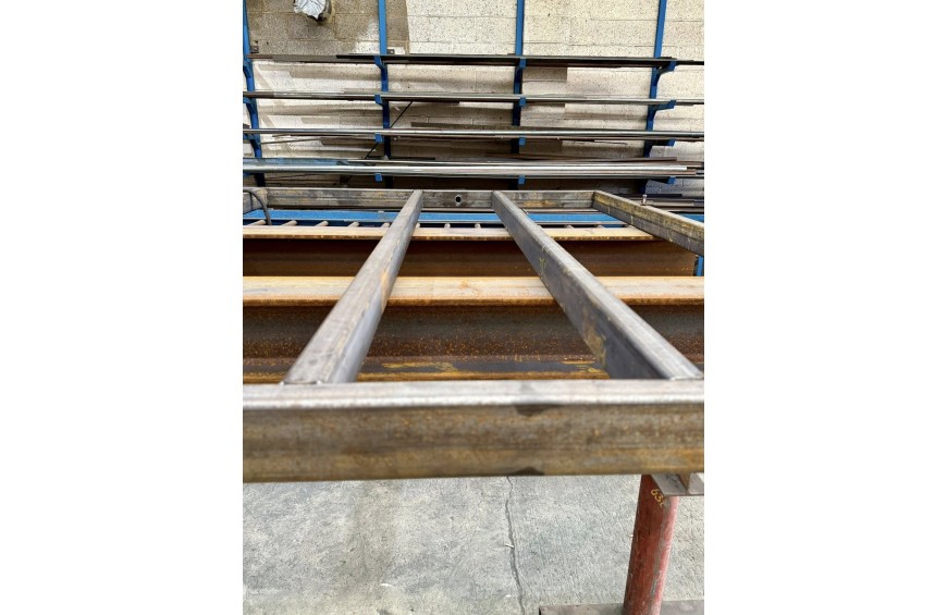
A Parallel Flange Channel is a structural steel section with a distinctive C-shaped cross-section, consisting of a vertical web with flanges projecting from one side only. Unlike the symmetrical I-section of Universal Beams where flanges extend equally on both sides of the web, PFC flanges are all on the same side, creating an open channel profile.
The "parallel flange" designation distinguishes modern PFCs from older tapered flange channels where the flange thickness decreased toward the outer edge. Parallel flanges maintain constant thickness throughout their width, providing better bearing surfaces for connections and more predictable structural behavior.
UK PFC designations follow a straightforward nomenclature. A section designated 230 x 90 x 32 PFC indicates a nominal depth of 230mm, a flange width of 90mm, and a mass of 32 kilograms per meter. Like other structural sections, these are nominal dimensions with actual measurements varying slightly from the rounded figures used for designation purposes.
Common PFC sizes in UK construction range from modest 100mm depth sections weighing around 10 kg/m up to substantial 430mm sections at 65 kg/m. The majority of applications draw from the middle range, with 150mm to 300mm depth channels proving most versatile for typical construction scenarios.
Geometric Properties and Structural Behavior
The asymmetric geometry of PFC sections creates structural characteristics fundamentally different from symmetric I-sections, and understanding these differences is essential to proper application.
Eccentric neutral axis represents the most significant geometric consequence of the C-shape. Unlike Universal Beams where the neutral axis runs through the center of the web, a PFC's neutral axis is offset toward the flanged side. This means the section's centroid doesn't align with the web centerline, which has important implications for connection design and load application.
When loads are applied through the channel's shear center—a point that doesn't coincide with the centroid—the section bends without twisting. However, loads applied away from the shear center induce torsional moments in addition to bending, complicating the structural behavior. This sensitivity to load position requires careful detailing but can be managed effectively with proper design.
Lower torsional rigidity compared to closed sections or symmetric open sections makes PFCs less resistant to twisting. A Universal Beam, with flanges on both sides providing balanced restraint, resists torsion far more effectively than a channel. This limitation restricts PFC use in applications where significant torsional loading occurs or where members are unrestrained against twisting.
Directional strength variation is more pronounced in channels than in UBs. While all I-sections have strong and weak axes, the asymmetry of PFCs creates a more complex stress distribution during bending. The section is most efficient when bending occurs about the axis parallel to the web, with the flanges in tension or compression. Bending about the weak axis produces less favorable stress patterns.
Shear center location outside the section profile means that loads applied through the web face create torsional effects unless specifically positioned. Understanding shear center location becomes important in precise applications or where deflection under eccentric loading must be predicted accurately.
Despite these complexities, PFCs remain highly effective structural elements when used appropriately. Their limitations become advantages in applications where the open C-shape provides functional benefits that closed or symmetric sections cannot match.
Key Advantages of PFC Channels
The distinctive geometry of channels creates several practical advantages that make them preferable to conventional beams in specific circumstances.
Single-sided access for connections represents perhaps the most significant practical advantage. The open back of a channel allows bolts to be installed from one side and accessed for tightening without requiring access behind the member. This proves invaluable when channels are installed against walls, attached to existing structures, or positioned where the back face is inaccessible. A Universal Beam requires access to both sides for bolting, which often proves impossible in renovation work or tight spaces.
Face-mounting capability allows channels to be fixed directly to flat surfaces like concrete walls, masonry, or existing steelwork using the web as a continuous bearing surface. The channel can be welded or bolted along its entire length, providing uniform load transfer that's difficult to achieve with other section types. This makes channels ideal for supporting structures attached to walls or for creating tracks and guides in moving systems.
Nested and back-to-back configurations enable creative structural assemblies. Two channels positioned back-to-back with webs touching create an I-section with adjustable spacing, allowing designers to fine-tune section properties for specific applications. Channels can also nest partially within each other to create compact assemblies or adjustable systems where relative position matters.
Efficient edge beams benefit from the channel's ability to provide torsional restraint when concrete slabs or other construction bears against the back of the web. The slab acts as a torsional brace, stabilizing the channel and allowing it to develop its full bending capacity. Universal Beams at slab edges often require additional torsional bracing that channels obtain naturally from the supported construction.
Lower profile in certain orientations results when channels are rotated with flanges horizontal. This configuration creates a low-height beam where depth is severely constrained, though at the cost of reduced bending capacity. The orientation flexibility provides design options unavailable with conventional beams.
Ease of modification for service penetrations or attachments benefits from the open back. Brackets, hangers, or equipment can be attached to the web without drilling through flanges or compromising structural integrity as severely as would occur with closed sections. The channel geometry makes adding or modifying attachments more forgiving.
When to Use PFC Channels Instead of Universal Beams
Several application categories strongly favor channels over conventional beam sections, each exploiting specific advantages of the C-shaped profile.
Wall-mounted supports and cantilevers represent classic channel applications. Supporting canopies, balconies, or equipment platforms from building facades typically requires structural members fixed to the wall face. Channels bolt or weld directly to the wall with their web providing continuous bearing, while the flanges project outward to carry loading. Achieving equivalent support with Universal Beams would require complex bracket systems and wouldn't provide the same load distribution.
Edge beams for concrete slabs often employ channels positioned with the web against the slab edge and flanges projecting below. This configuration supports the slab edge while providing a clean soffit profile. The slab bears against the channel web, preventing torsional rotation and allowing the channel to function efficiently. Edge beams also provide attachment points for cladding, barriers, or architectural features.
Secondary framing attached to primary structure benefits from channels when one structure must be suspended from or attached to another. Channels can be bolted to existing columns or beams with their webs, then project outward to carry secondary loads. This creates clear load paths without requiring penetrations through primary structure or access to hidden faces.
Lifting beams and spreader bars in temporary works or permanent lifting installations commonly use channels or fabricate them into box sections. The open back allows for inspection of the full length, facilitates attachment of lifting points, and enables straightforward fabrication of specialized lifting devices.
Support framing for conveyor systems, pipework, or cable trays exploits channels' ability to create continuous support rails. Channels can run for extended lengths with equipment attached at any point along the web, providing flexibility for layout modifications without structural alterations. The single-sided connection access simplifies installation and adjustment.
Stair stringers and structural supports in constrained spaces take advantage of channels' asymmetric profile. A stair stringer can be detailed with the channel web against a wall and flanges supporting treads, creating an efficient structure with minimal projection. Similarly, structural supports in confined plant rooms or service areas benefit from face-mounting capability.
Trench covers and grating supports employ channels as support members positioned with flanges upward to create ledges for gratings or covers to rest upon. The geometry naturally creates the recessed ledge needed without additional fabrication.
Crane rails and moving equipment tracks historically used channels, though specialized sections now exist for many applications. The channel profile provides lateral guidance while supporting vertical loads, making it suitable for applications where equipment must travel along defined paths.
When Universal Beams or Columns Are Better Choices
Despite their advantages in specific applications, channels prove inferior to conventional sections in many common structural scenarios.
Primary building frames almost universally employ Universal Beams and Columns rather than channels. The symmetric geometry of UBs and UCs provides balanced bending resistance, better torsional rigidity, and more straightforward connection details. Frame stability and load distribution work far more predictably with symmetric sections.
Long-span floor beams carrying uniform loads perform better as Universal Beams. The symmetric flange arrangement optimizes material distribution for pure bending, providing superior capacity-to-weight ratios. Channels would require significantly more steel to achieve equivalent performance in straightforward beam applications.
Columns carrying axial loads demand Universal Columns with their broad flanges and compact cross-sections that resist buckling efficiently. Channel sections, with narrow flanges and asymmetric geometry, prove inefficient for compression members except in very specific applications where their other properties provide compensating advantages.
Situations requiring high torsional resistance rule out channels in favor of closed sections (rectangular or circular hollow sections) or the superior torsional performance of I-sections. Any application where twisting moments are significant should consider alternatives to channels.
Beam-to-column connections in moment frames work more straightforwardly with Universal Beams and Columns. The symmetric geometry allows standard connection details with predictable behavior. Connecting channels in moment-resisting arrangements requires additional consideration of eccentricity and torsional effects.
Applications where access exists to all faces remove one of the channel's key advantages, making conventional sections more appropriate on structural efficiency grounds alone.
Design Considerations Specific to PFC Channels
Proper channel design requires attention to several factors unique to the section geometry that wouldn't concern engineers designing with symmetric sections.
Load application position critically affects channel behavior. Loads should ideally be applied through the shear center to avoid inducing torsion, or the channel must be restrained against twisting at sufficient intervals. In practice, this often means positioning loads at the web face or providing torsional bracing from the supported construction.
Lateral-torsional buckling requires particular attention with unrestrained channels. The section's low torsional rigidity makes it susceptible to buckling that combines lateral displacement with twisting. Design codes provide methods for calculating reduced capacity, but the penalties can be severe for long unrestrained lengths. Continuous or frequent lateral restraint dramatically improves channel performance.
Eccentricity effects in connections must be considered where the load path doesn't align with the section's neutral axis. Bolted connections to the web face create moments that induce additional stresses beyond simple bending or shear. These effects are manageable with proper analysis but mustn't be overlooked.
Web bearing and crippling can govern capacity where concentrated loads bear against the relatively thin channel web. Local reinforcement through bearing stiffeners or doubler plates may be necessary where point loads or reactions are large relative to web thickness and depth.
Serviceability deflection calculations should account for the channel's lower stiffness compared to similar-mass Universal Beams. The less efficient material distribution means channels deflect more under equivalent loading, which may govern design in deflection-sensitive applications.
Connection details require more careful consideration than with symmetric sections. Standard beam connections may not transfer directly to channel applications. Engineers must detail connections accounting for the asymmetric geometry, potential torsional effects, and the specific load paths created by channel configurations.
PFC Sizes and Selection
UK PFC sections are available in a range that covers most light to medium structural applications, though the size range is narrower than Universal Beams.
Small sections including 100 x 50 x 10 PFC, 125 x 65 x 15 PFC, and 150 x 75 x 18 PFC suit light-duty applications like small cantilevers, equipment supports, and architectural details. These sections are easily handled and installed, making them practical for minor works.
Medium sections like 180 x 75 x 20 PFC, 200 x 75 x 23 PFC, 230 x 90 x 32 PFC, and 260 x 90 x 35 PFC represent the workhorse range for typical construction applications. These sizes handle substantial loads while remaining manageable and economical.
Large sections including 300 x 100 x 46 PFC, 380 x 100 x 54 PFC, and 430 x 100 x 64 PFC serve heavy-duty applications and long spans. These deeper sections approach or exceed the capacity of many medium Universal Beams when properly restrained and loaded.
Selection should consider both the required structural capacity and the specific advantages channels provide for the application. A channel might be chosen despite requiring a heavier section than an equivalent Universal Beam if the connection advantages or geometric properties justify the modest material increase.
Back-to-Back Channel Assemblies
Two channels positioned back-to-back with webs in contact or separated by packing create a built-up I-section with properties that can be adjusted by varying the spacing. This configuration serves several purposes.
Creating custom I-sections with specific properties allows designers to achieve capacities or proportions unavailable in standard Universal Beam ranges. Varying the spacing between channels adjusts the overall width and section properties to suit specific requirements.
Adjustable connection geometry results from the ability to position channels at any spacing. This flexibility helps match connection dimensions to existing steelwork or architectural requirements without resorting to custom fabrication.
Improved torsional rigidity compared to single channels results from the box-like geometry created by back-to-back positioning. While not matching closed sections, the configuration dramatically improves torsional performance over single channels.
Simplified long-span transportation and handling becomes possible by delivering channels separately and assembling them on site. Two 6-meter channels are easier to transport and maneuver than a single 6-meter Universal Beam of equivalent capacity.
Progressive installation in constrained spaces allows one channel to be positioned and secured, followed by the second channel once access allows. This flexibility proves valuable in tight spaces or complex renovation scenarios.
Back-to-back channel design requires proper connection between the channels through bolting or welding at sufficient intervals to ensure composite action. The channels must act together rather than as two independent members, which demands appropriate connection spacing and detailing.
Fabrication and Connection Details
Channel fabrication and connection require techniques adapted to the asymmetric geometry, though most operations remain straightforward with appropriate planning.
Welding to channels typically occurs along the web face or to flange tips. Web welding requires access to the channel back, which may be restricted depending on installation configuration. Flange welding must account for the relatively narrow flange width and ensure adequate weld size without excessive distortion.
Bolted connections exploit the channel's main advantage by allowing single-sided installation. Bolts pass through the web with nuts or anchor systems on the back face. Where the back remains accessible during installation but not afterward, bolts can be tightened conventionally. Where back access never exists, specialized anchor systems or threaded inserts enable bolting.
Bearing stiffeners attached to channel webs require doubler plates on both sides of the web or heavy stiffeners welded to the web and flanges. The stiffener configuration must account for the asymmetric geometry and ensure adequate load transfer without causing local distortion.
End plates welded to channel ends for connections typically span the full width between flange tips. The plate thickness and welding must transfer end reactions reliably, accounting for the eccentric load path through the channel cross-section.
Cleats and brackets attached to channels should be designed recognizing that the connection may induce torsional moments if positioned eccentrically. Simple shear connections might create torsion that restrained channels can resist but unrestrained channels cannot.
Cost and Availability Considerations
PFC channels generally cost slightly more per tonne than Universal Beams of similar mass due to lower production volumes and less standardized rolling. However, the total cost difference for typical quantities remains modest and often proves irrelevant compared to the connection and installation advantages channels provide for appropriate applications.
Availability varies with section size and local stockholder inventory. Common sizes in the 150mm to 260mm range are widely stocked, while very small or very large sections may require ordering with associated lead times. Projects should verify availability early in design to avoid schedule impacts.
Fabrication costs for channels are comparable to Universal Beams for simple operations but may increase where specialized details are required to address asymmetric geometry. Standard shop practices handle channels routinely, though fabricators appreciate early consultation on complex channel details.
Alternatives to Consider
Several alternative sections compete with or complement PFC channels in various applications, and designers should consider whether channels truly represent the optimal choice.
Rectangular or square hollow sections (RHS/SHS) provide superior torsional rigidity and more efficient structural performance in many applications where channels might be considered. The closed section eliminates many of the complications associated with channel asymmetry while providing clean aesthetics. However, hollow sections sacrifice the single-sided connection advantage and face-mounting capability that channels offer.
Angle sections suit some applications where channels might be considered, particularly for edge members or attachments. Two angles can be assembled into configurations approximating channel geometry while providing even greater connection flexibility. Angles sacrifice the continuous web that gives channels their stiffness and load distribution capability.
Universal Beams with specialized connections sometimes prove more efficient than channels even where access is restricted. Custom brackets, extended end plates, or innovative connection details can overcome access limitations while exploiting the superior structural efficiency of symmetric sections.
Cold-formed sections including lipped channels offer lighter-weight alternatives for applications where loads are modest and the increased deflection of thin-walled sections is acceptable. Cold-formed channels provide similar geometric advantages at lower mass but with reduced capacity and stiffness.
The choice between channels and alternatives should weigh structural efficiency, connection practicality, fabrication complexity, cost, and the specific requirements of each application. Channels excel where their distinctive advantages align with project needs but shouldn't be specified simply from habit or without considering whether alternatives might perform better.
Conclusion
Parallel Flange Channels occupy a specific but important niche in structural steel construction, providing solutions to problems where Universal Beams and Columns would prove awkward or inefficient. Their asymmetric C-shaped geometry creates both limitations and advantages—lower torsional rigidity and eccentric neutral axis position complicate design, while single-sided connection access and face-mounting capability enable elegant solutions to common construction challenges.
The key to effective channel specification lies in recognizing situations where their unique properties provide genuine value. Wall-mounted cantilevers, edge beams, secondary framing attachments, and support systems in constrained spaces all benefit from channel geometry in ways that justify accepting the structural complications asymmetry creates. Conversely, primary framing, long-span floors, columns, and other applications demanding maximum structural efficiency per unit weight should employ Universal Beams or Columns unless specific circumstances favor channels.
Understanding when to specify channels instead of conventional beam sections requires balancing structural performance against practical construction considerations. Channels represent a specialized tool in the structural designer's repertoire—not appropriate for every application, but invaluable when circumstances demand the particular combination of properties only the C-shaped profile provides. Proper channel specification comes from recognizing these circumstances and designing details that exploit channel advantages while managing their limitations.
Submit comment Cancel Reply